Introduction:
The PID controller has several important functions: it provides feed- back; it has the ability to eliminate steady state offsets through integral action; it can anticipate the future through derivative action. PID controllers are sufficient for many control problems, particularly when process dynamics are benign and the performance requirements are modest. PID controllers are found in large numbers in all industries. The controllers come in many different forms. There are standalone systems in boxes for one or a few loops, which are manufactured by the hundred thousands yearly. PID control is often combined with logic, sequential machines, se- lectors, and simple function blocks to build the complicated automation systems used for energy production, transportation, and manufacturing. Many sophisticated control strategies, such as model predictive control, are also organized hierarchically. PID control is used at the lowest level; the multivariable controller gives the setpoints to the controllers at the lower level. The PID controller can thus be said to be the “bread and butter” of control engineering. It is an important component in every control engineer’s toolbox.
What Is A PID Controller?
PID stand for Proportional-Integral-Derivative controller this device mostly used in industrial automation .PID controllers typically use control loop feedback in industrial and control systems applications.
Firstly We Understand Control System :
feedback control system: The controls in an automated system can be either closed loop or open loop. A closed loop control system, also known as a feedback control system, is one in which the output variable is compared with an input parameter, and any difference between the two is used to drive the output into agreement with the input. As shown in Figure.

a closed-loop control system consists of six basic elements: (1) input parameter, (2) process, (3) output variable, (4) feedback sensor, (5) controller, and (6) actuator. The input parameter (i.e., set point) represents the desired value of the output. In a home temperature control system, the set point is the desired thermostat setting. The process is the operation or function being controlled. In particular, it is the output variable that is being controlled in the loop. In the present discussion, the process of interest is usually a manufacturing operation, and the output variable is some process variable, perhaps a critical performance measure in the process, such as temperature or force or flow rate. A sensor is used to measure the output variable and close the loop between input and output. Sensors perform the feedback function in a closed-loop control system. The controller compares the output with the input and makes the required adjustment in the process to reduce the difference between them. The adjustment is accomplished using one or more actuators, which are the hardware devices that physically carry out the control actions.
open-loop control system: an open-loop control system operates without the feedback loop, as in Figure 2 In this case, the controls operate without measuring the output variable, so no comparison is made between the actual value of the output and the desired input parameter. The controller relies on an accurate model of the effect of its actuator on the process variable. With an open-loop system, there is always the risk that the actuator will not have the intended effect on the process, and that is the disadvantage of an open-loop system. Its advantage is that it is generally simpler and less expensive than a closed-loop system

How PID Controller Work:
A PID controller continuously calculates an error value e(t) as the difference between a desired set point (SP) and a measured process variable (PV) and applies a correction based on proportional, integral, and derivative terms (denoted P, I, and D respectively) which give the controller its name.
Controller error(e(t)) at current time t is computed as set-point(SP) minus measured process variable as . e(t) = SP-PV.
In a typical PID control loop, the controller continuously calculates the error as the difference between the process variable (current value) and the setpoint (desired value). It then adjusts the control output (such as a valve position or motor speed) using the P, I, and D terms to minimize the error.
PID Components:
PID controllers have three control modes:
- Proportional Control
- Integral Control
- Derivative Control
- Each of the three modes reacts differently to the error. The amount of response produced by each control mode is adjustable by changing the controller’s tuning settings.
Proportional Controller:
In a proportional controller the output (also called the actuating/control signal) is directly proportional to the error signal. The position of Kp can be as shown in Fig

Control signal = Kp * e(t)
If the error signal is a voltage, and the control signal is also a voltage, then a proportional controller is just an amplifier.
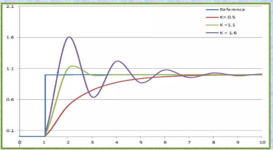
In a proportional controller, steady state error tends to depend inversely upon the proportional gain, so if the gain is made larger the error goes down as in . SSE=1/(1+ KG (0)) Where SSE is the steady state error Proportional controller helps in reducing the steady state error, thus makes the system more stable. Slow response of the over damped system can be made faster with the help of these controllers. P controller has the advantage of reducing down the steady state error of the system, but along with that it also has some serious disadvantages. These properties can be shown in Fig.

Example: If you’re trying to maintain the temperature of an oven at 100°C, and the temperature is currently 90°C, the proportional term will apply a correction proportional to the 10°C difference to bring it back to 100°C.
Disadvantages of P Controller
- Due to presence of these controllers we have some offsets in the system.
- Proportional controllers also increase the maximum overshoot of the system.
- It directly amplifies process noise
- To avoid these errors and to make the controller more accurate and practical, we use the advanced and modified version of it known as the Proportional Integral Controllers (PI) and Proportional Derivative Controllers (PD).
Integral Controller :
An integral term increases action in relation not only to the error but also the time for which it has persisted. So, if applied force is not enough to bring the error to zero, this force will be increased as time passes. A pure “I” controller could bring the error to zero, however, it would be both slow reacting at the start (because action would be small at the beginning, needing time to get significant), brutal (the action increases as long as the error is positive, even if the error has started to approach zero), and slow to end (when the error switches sides, this for some time will only reduce the strength of the action from “I”, not make it switch sides as well), prompting overshoot and oscillations (see Fig.4). Moreover, it could even move the system out of zero error: remembering that the system had been in error, it could prompt an action when not needed. An alternative formulation of integral action is to change the electric current in small persistent steps that are proportional to the current error. Over time the steps accumulate and add up dependent on past errors this is the discrete-time equivalent to integration

Example: If the oven temperature has been consistently below 100°C for a period, the integral action will add more correction based on the cumulative error to bring it up to the setpoint.
Derivative Controller:
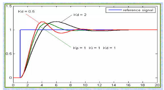
A derivative term does not consider the error (meaning it cannot bring it to zero: a pure D controller cannot bring the system to its set-point), but the rate of change of error, trying to bring this rate to zero. It aims at flattening the error trajectory into a horizontal line, damping the force applied, and so reduces overshoot (error on the other side because too great applied force). Applying too much impetus when the error is small and is reducing will lead to overshoot. After overshooting, if the controller were to apply a large correction in the opposite direction and repeatedly overshoot the desired position, the output would oscillate around the set-point in either a constant, growing, or decaying sinusoid. If the amplitude of the oscillations increase with time, the system is unstable. If they decrease, the system is stable. If the oscillations remain at a constant magnitude, the system is marginally stable. This can be illustrated in Fig

Example: If the oven’s temperature is rising too quickly towards the setpoint, the derivative term will apply a correction to slow down the heating to avoid overshooting the target.
PID:
Although a PID controller has three control terms, some applications use only one or two terms to provide the appropriate control. This is achieved by setting the unused parameters to zero and is called a PI, PD, Por I controller in the absence of the other control actions. PI controllers are fairly common, since derivative action is sensitive to measurement noise, whereas the absence of an integral term may prevent the system from reaching its target value.

Limitations of PID control
While PID controllers are applicable to many control problems, and often perform satisfactorily without any improvements or only coarse tuning, they can perform poorly in some applications, and do not in general provide optimal control. The fundamental difficulty with PID control is that it is a feedback control system, with constant parameters, and no direct knowledge of the process, and thus overall performance is reactive and a compromise. While PID control is the best controller in an observer without a model of the process, better performance can be obtained by overtly modeling the actor of the process without resorting to an observer. PID controllers, when used alone, can give poor performance when the PID loop gains must be reduced so that the control system does not overshoot, oscillate or hunt about the control set point value.
They also have difficulties in the presence of non-linearities, may trade-off regulation versus response time, do not react to changing process behavior (say, the process changes after it has warmed up), and have lag in responding to large disturbances. The most significant improvement is to incorporate feed-forward control with knowledge about the system, and using the PID only to control error. Alternatively, PIDs can be modified in more minor ways, such as by changing the parameters (either gain scheduling in different use cases or adaptively modifying them based on performance), improving measurement (higher sampling rate, precision, and accuracy, and low-pass filtering if necessary), or cascading multiple PID controllers.
Applications of PID Controllers:
- Temperature Control: Maintaining a constant temperature in ovens, furnaces, or refrigeration systems.
- Speed Control: Regulating the speed of motors, pumps, and fans in various automation systems.
- Pressure Control: Managing the pressure in pipelines, hydraulic systems, or gas distribution systems.
- Flow Control: Controlling the flow of liquids or gases in chemical plants or water treatment facilities.
- Positioning Systems: Achieving precise positioning in robotics or CNC machines.
