Introduction:
In this article we learn about ladder logic rules for plc programing if you are working in plc this article more important for you. the ladder rules help you troubleshot error . A Ladder diagram is a symbolic and schematic representation of both the process hardware and process control. Its called a ‘Ladder’ because all the devices are connected across the supply lines making it look like a ladder. Each parallel connection is called a ‘Rung’, it can contain many inputs but only one output.
What is Ladder Language :
is a programming language used to program PLCs (programmable logic controllers). It is a graphical PLC programming language that uses symbols to represent logical operations. Ladder logic is composed of logical steps, forming what looks like a ladder-hence the name “ladder logic.
Inputs Can Be in Series or Parallel
In this rule in ladder language, we use input contact in only series and parallel. This flexibility allows programmers to write complex logic. means series circuit is also known as AND GATE when one and more condition is true, then output is true. OR GATE, also known as a parallel circuit in or logic, when one condition is true, then the output is true.


Outputs Only in Parallel
In this rule, the output coil used only in parallel connection output can not be used in series connection. In the shown figure, if the M0.0 is in a high condition, then all output will be high.

One input used in multiple time:
In this ladder rule, input we can use multiple times to write a logic, but output cannot use multiple times.

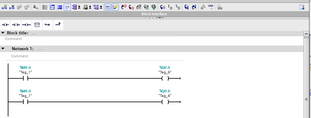
One output can not be used in multiple time :
In this ladder rule, we cannot use output multiple times. If we use multiple-time output, then output will confuse which condition I will be on.

Input address can not used as an output coil :
In this rule, we cannot use the input address to output the coil. because input is a defined reading signal from sensors.

Output address can not used in input address:
In this rule, we cannot use the output address in the input coil. Output addresses are designated for controlling devices, while input addresses are meant for receiving signals from sensors.

This is all basic rule of plc programing
