WHAT IS MACHINE VISION?
According to the Automated Imaging Association (AIA), machine vision encompasses all industrial and non-industrial applications in which a combination of hardware and software provide operational guidance to devices in the execution of their functions based on the capture and processing of images. Though industrial computer vision
uses many of the same algorithms and approaches as academic/educational and governmental/military applications of computer vision, constraints are different. Industrial vision systems demand greater robustness, reliability, and stability compared with an academic/educational vision system and typically cost much less than those used in governmental/military applications. Therefore, industrial machine vision implies low cost, acceptable accuracy, high robustness, high reliability, and high mechanical, and temperature stability
Machine vision systems rely on digital sensors protected inside industrial cameras with specialized optics to acquire images, so that computer hardware and software can process, analyze, and measure various characteristics for decision making.
Machine vision systems can also perform objective measurements, such as determining a spark plug gap or providing location information that guides a robot to align parts in a manufacturing process.
BENEFITS OF MACHINE VISION
Where human vision is best for qualitative interpretation of a complex, unstructured scene, machine vision excels at quantitative measurement of a structured scene because of its speed, accuracy, and repeatability. For example, on a production line, a machine vision system can inspect hundreds, or even thousands, of parts per minute.
A machine vision system built around the right camera resolution and optics can easily inspect object details too small to be seen by the human eye.
In removing physical contact between a test system and the parts being tested, machine vision prevents part damage and eliminates the maintenance time and costs associated with wear and tear on mechanical components. Machine vision brings additional safety and operational benefits by reducing human involvement in a manufacturing process.
Moreover, it prevents human contamination of clean rooms and protects human workers from hazardous environments
MACHINE VISION APPLICATIONS
Typically the first step in any machine vision application, whether the simplest assembly verification or a complex 3D robotic bin-picking, is for pattern matching technology to find the object or feature of interest within the camera’s field of view. Locating the object of interest often determines success or failure. If the pattern matching software
tools can not precisely locate the part within the image, then it can not guide, identify, inspect, count, or measure the part. While finding a part sounds simple, differences in its appearance in actual production environments can make that step extremely challenging.
To achieve accurate, reliable, and repeatable results, a vision system’s part location tools must include enough intelligence to quickly and accurately compare training patterns to the actual objects (pattern matching) moving down a production line. Part location is the critical first step in the four major categories of machine vision
applications. The categories are guidance, identification, gauging, and inspection, which can be remembered by the acronym (GIGI).
GUIDANCE
Guidance may be done for several reasons. First, machine vision systems can locate the position and orientation of a part, compare it to a specified tolerance, and ensure it’s at the correct angle to verify proper assembly. Next, guidance can be used to report the location and orientation of a part in 2D or 3D space to a robot or machine controller, allowing the robot to locate the part or the machine to align the part. Machine vision guidance achieves far greater speed and accuracy than manual positioning in tasks such as arranging parts on or off pallets, packaging parts off a conveyor belt, finding and aligning parts for assembly with other components, placing parts on a work shelf, or removing parts from bins
Guidance can also be used for alignment to other machine vision tools. This is a very powerful feature of machine vision because parts may be presented to the camera in unknown orientations during production. By locating the part and then aligning the other machine vision tools to it, machine vision enables automatic tool fixturing. This involves locating key features on a part to enable precise positioning of caliper, blob, edge, or other vision software tools so that they correctly interact with the part. This approach enables manufacturers to build multiple products on the same production line and reduces the need for expensive hard tooling to maintain part position during inspection.
IDENTIFICATION
A machine vision system for part identification and recognition reads barcodes (1-D), data matrix codes (2-D), direct part marks (DPM), and characters printed on parts, labels, and packages. An optical character recognition (OCR) system reads alphanumeric characters without prior knowledge, whereas an optical character verification (OCV) system confirms the presence of a character string. Additionally, machine vision systems can identify parts by locating a unique pattern or identify items based on color, shape, or size.
DPM applications mark a code or character string directly on to the part. Manufacturers in all industries commonly use this technique for error-proofing, enabling efficient containment strategies, monitoring process control and quality-control metrics, and quantifying problematic areas in a plant such as bottlenecks. Traceability by direct part
marking improves asset tracking and part authenticity verification. It also provides unit level data to drive superior technical support and warranty repair service by documenting the genealogy of the parts in a sub-assembly that make up the finished product.

GAUGING
A machine vision system for gauging calculates the distances between two or more points or geometrical locations on an object and determines whether these measurements meet specifications. If not, the vision system sends a fail signal to the machine controller, triggering a reject mechanism that ejects the object from the line. In practice, a fixed-mount camera captures images of parts as they pass the camera’s field of view and the system uses software to calculate distances between various points in the image. Because many machine vision systems can measure object features to within 0.0254 millimeters, they address a number of applications traditionally handled by contact gauging.
INSPECTION
A machine vision system for inspection detects defects, contaminants, functional flaws, and other irregularities in manufactured products. Examples include inspecting tablets of medicine for flaws, displays to verify icons or confirm pixel presence, or touch screens to measure the level of backlight contrast. Machine vision can also inspect products for completeness, such as ensuring a match between product and package in the food and pharmaceutical industries, and checking safety seals, caps, and rings on bottles.
COMPONENTS OF MACHINE VISION
The major components of a machine vision system include the lighting, lens, image sensor, vision processing, and communications. Lighting illuminates the part to be inspected allowing its features to stand out so they can be clearly seen by camera. The lens captures the image and presents it to the sensor in the form of light. The sensor in
a machine vision camera converts this light into a digital image which is then sent to the processor for analysis.
Vision processing consists of algorithms that review the image and extract required information, run the necessary inspection, and make a decision. Finally, communication is typically accomplished by either discrete I/O signal or data sent over a serial connection to a device that is logging information or using it.
LIGHTING
Lighting is one key to successful machine vision results. Machine vision systems create images by analyzing the reflected light from an object, not by analyzing the object itself. A lighting technique involves a light source and its placement with respect to the part and the camera. A particular lighting technique can enhance an image such that
it negates some features and enhances others, by silhouetting a part which obscures surface details to allow measurement of its edges, for example.

Back lighting
Back lighting enhances an object’s outline for applications that need only external or edge
measurements. Back lighting helps detect shapes and makes dimensional measurements
more reliable.

Axial diffuse lighting
Axial diffuse lighting couples light into the optical path from the side (coaxially). A semitransparent mirror illuminated from the side, casts light downwards on the part. The part reflects the light back to the camera through the semi-transparent mirror resulting in a very
evenly illuminated and homogeneous looking image.

Structured light
Structured light is the projection of a light pattern (plane, grid, or more complex shape) at a known angle onto an object. It can be very useful for providing contrast-independent surface inspections, acquiring dimensional information and calculating volume.

Dark-field illumination
Directional lighting more easily reveals surface defects and includes dark-field and brightfield illumination. Dark-field illumination generally preferred for low-contrast applications. In dark-field illumination, specular light is reflected away from the camera, and diffused light from surface texture and elevation changes are reflected into the camera.

Bright-field illumination
Bright-field illumination is ideal for high-contrast applications. However, highly directional light sources such as high-pressure sodium and quartz halogen may produce sharp shadows and generally do not provide consistent illumination throughout the entire field of
view. Consequently, hot-spots and specular reflections on shiny or reflective surfaces may require a more diffused light source to provide even illumination in the brightfield.

Diffused dome lighting
Diffused dome lighting gives the most uniform illumination of features of interest, and can mask irregularities that are not of interest and may be confusing to the scene
LENSES
The lens captures the image and delivers it to the image sensor in the camera. Lens will vary in optical quality and price, the lens used determines the quality and resolution of the captured image. Most vision system cameras offer two main types of lenses: interchangeable lenses and fixed lenses. Interchangeable lenses are typically C-mounts
or CS-mounts. The right combination of lens and extension will acquire the best possible image. A fixed lens as part of a standalone vision system typically uses autofocus, which could be either a mechanically adjusted lens or a liquid lens that can automatically focus on the part. Autofocus lenses usually have a fixed field of view at a given distance.
IMAGE SENSOR
The camera’s ability to capture a correctly-illuminated image of the inspected object depends not only on the lens, but also on the image sensor within the camera. Image sensors typically use a charge coupled device (CCD) or complementary metal oxide semiconductor (CMOS) technology to convert light (photons) to electrical signals
(electrons). Essentially the job of the image sensor is to capture light and convert it to a digital image balancing noise, sensitivity and dynamic range. The image is a collection of pixels. Low light produces dark pixels, while bright light creates brighter pixels. It’s important to ensure the camera has the right sensor resolution for the application.
The higher the resolution, the more detail an image will have, and the more accurate measurements will be. Part size, inspection tolerances, and other parameters will dictate the required resolution.
VISION PROCESSING
Processing is the mechanism for extracting information from a digital image and may take place externally in a PC-based system, or internally in a standalone vision system. Processing is performed by software and consists of several steps. First, an image is acquired from the sensor. In some cases, pre-processing may be required to optimize the image and ensure that all the necessary features stand out. Next, the software locates the specific features, runs measurements, and compares these to the specification. Finally, a decision is made and the results are communicated. While many physical components of a machine vision system (such as lighting) offer comparable specifications, the vision system algorithms set them apart and should top the list of key components to evaluate when comparing solutions. Depending on the specific system or application, vision software configures camera parameters, makes the pass-fail decision, communicates with the factory floor, and supports HMI
development.
COMMUNICATIONS
Since vision systems often use a variety of off-the-shelf components, these items must coordinate and connect to other machine elements quickly and easily. Typically this is done by either discrete I/O signal or data sent over a serial connection to a device that is logging information or using it. Discrete I/O points may be connected to a programmable logic controller (PLC), which will use that information to control a work cell or an indicator such as a stack light or directly to a solenoid which might be used to trigger a reject mechanism. Data communication by a serial connection can be in the form of a conventional RS232 serial output, or Ethernet. Some systems employ a higher-level industrial protocol like Ethernet/IP, which may be connected to a device like a monitor or other operator
interface to provide an operator interface specific to the application for convenient process monitoring and control.
DIFFERENT TYPES OF MACHINE VISION SYSTEMS
There are 3 categories of machine vision systems: 1D, 2D and 3D.
1D VISION SYSTEMS
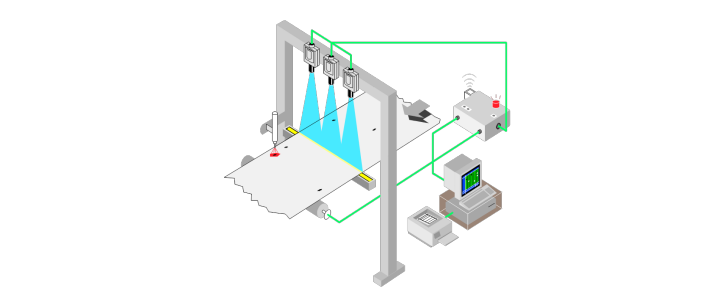
1D vision analyzes a digital signal one line at a time instead of looking at a whole picture at once, such as assessing the variance between the most recent group of ten acquired lines and an earlier group. This technique commonly detects and classifies defects on materials manufactured in a continuous process, such as paper, metals, plastics, and
other non-woven sheet or roll goods, as shown in Figure
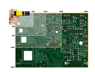
2D VISION SYSTEMS
Most common inspection cameras perform area scans that involve capturing 2D snapshots in various resolutions, as shown in Figure .Another type of 2D machine vision–line scan–builds a 2D image line by line,
AREA SCAN VS. LINE SCAN
In certain applications, line scan systems have specific advantages over area scan systems. For example, inspecting round or cylindrical parts may require multiple area scan cameras to cover the entire part surface. However, rotating the part in front of a single line scan camera captures the entire surface by unwrapping the image. Line scan systems fit more easily into tight spaces for instances when the camera must peek through rollers on a conveyor to view the bottom of a part. Line scan systems can also generally provide much higher resolution than traditional cameras. Since line scan systems require parts in motion to build the image, they are often well-suited for products in continuous motion.
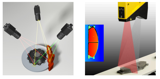
3D SYSTEMS
3D machine vision systems typically comprise multiple cameras or one or more laser displacement sensors. Multi-camera 3D vision in robotic guidance applications provides the robot with part orientation information. These systems involve multiple cameras mounted at different locations and “triangulation” on an objective position in 3-D space.