The Programable Logic Controller:
- A programmable logic controller (PLC) is a heart of control system. plc special form of microprocessor-based controller that uses a programmable memory to store instructions and to implement functions such as logic, sequencing, timing, counting and arithmetic in order to control machines and processes and are designed to be operated by engineers with perhaps a limited knowledge of computers and computing languages. They are not designed so that only computer programmers can set up or change the programs. Thus, the designers of the PLC have pre-programmed it so that the control program can be entered using a simple, rather intuitive, form of language. The term logic is used because programming is primarily concerned with implementing logic and switching operations.
- PLCs have the great advantage that the same basic controller can be used with a wide range of control systems. To modify a control system and the rules that are to be used, all that is necessary is for an operator to key in a different set of instructions. There is no need to rewire. The result is a flexible, cost effective, system which can be used with control systems which vary quite widely in their nature and complexity. PLCs are similar to computers but whereas computers are optimised for calculation and display tasks, PLCs are optimised for control tasks and the industrial environment.
- PLCs are:
- 1)Rugged and designed to withstand vibrations, temperature, humidity and noise.
- 2 )Have interfacing for inputs and outputs already inside the controller.
- 3 )Are easily programmed and have an easily understood programming language which is primarily concerned with logic and switching operation.
PLC benefits :
- 1)Increased Reliability: Once a program has been
written and tested, it can be easily downloaded
to other PLCs. - 2)More Flexibility: It is easier to create and change a pro
gram in a PLC than to wire and rewire a circuit. - 3)Lower Cost: PLCs were originally designed to re
place relay control logic, and the cost savings - 4)Communications Capability: A PLC can communicate with other controllers or computer equipment to perform such functions as supervisory control, data
gathering, monitoring devices and process parameters,
and download and upload of programs. - 5)Faster Response Time: PLCs are designed for high speed and real-time applications The programmable controller operates in real time.
- 6)Easier to Troubleshoot: PLCs have resident diagnostics and override functions that allow users to easily trace and correct software and hardware problems. To find and fi x problems, users can display the
control program on a monitor and watch it in real
time.
Plc Hardware:
Typically a PLC system has the basic functional components of processor unit, memory, power supply unit, input/output interface section, communications interface and the programming device. Figure shows the basic arrangement.
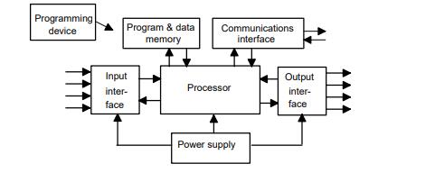
- 1) The processor unit or central processing unit (CPU) is the unit containing the microprocessor and this interprets the input signals and carries out the control actions, according to the program stored in its memory, communicating the decisions as action signals to the outputs.
2) The power supply unit is needed to convert the mains ac and dc voltage to the low dc voltage (5 V) necessary for the processor and the circuits in the input and output interface modules.
3) The programming device is used to enter the required program into the memory of the processor. The program is developed in the device and then transferred to the memory unit of the PLC.
4) The memory unit is where the program is stored that is to be used for the control actions to be exercised by the microprocessor and data stored from the input for processing and for the output for outputting.
5) The input and output sections are where the processor receives information from external devices and communicates information to external devices.
6)The communications interface is used to receive and transmit data on communication networks from or to other remote PLCs and devices.
Plc type:
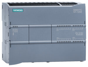
There are two common types of mechanical design for PLC systems; a single box, and the modular/rack types. The single box type (or, as sometimes termed, brick) is commonly used for small programmable controllers and is supplied as an integral compact package complete with power supply, processor, memory, and input/output units. Typically such a PLC might have 6, 8, 12 or 24 inputs and 4, 8 or 16 outputs and a memory which can store some 300 to 1000 instructions.
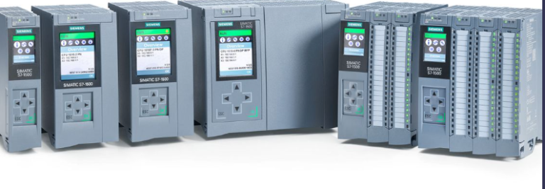
Rack type : Systems with larger numbers of inputs and outputs are likely to be modular and designed to fit in racks. The modular type consists of separate modules for power supply, processor, etc., which are often mounted on rails within a metal cabinet. The rack type can be used for all sizes of programmable controllers and has the various functional units packaged in individual modules which can be plugged into sockets in a base rack. The mix of modules required for a particular purpose is decided by the user and the appropriate ones then plugged into the rack. Thus it is comparatively easy to expand the number of input/output (I/O) connections by just adding more input/output modules or to expand the memory by adding more memory units.
Plc Program Scan:
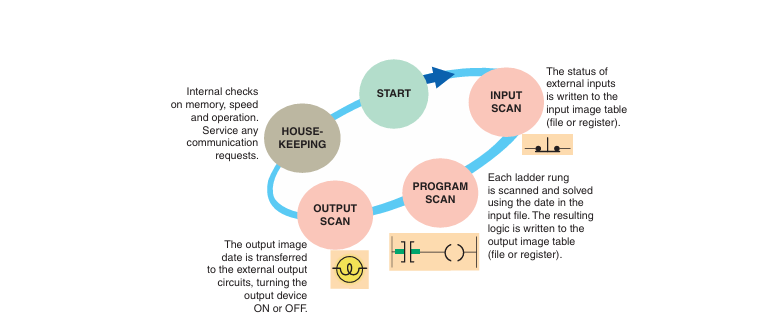
The time it takes to complete a scan cycle is called the scan cycle time and indicates how fast the controller can react to changes in inputs. The time required to make a single scan can vary from about 1 millisecond to 20 milliseconds. If a controller has to react to an input signal that changes states twice during the scan time, it is possible that the PLC will never be able to detect this change. For example, if it takes 8 ms for the CPU to scan a program, and an input contact is opening and closing every 4 ms, the program may not respond to the contact changing state. The CPU will detect a change if it occurs during the update of the input image table fi le, but the CPU will not
respond to every change. The scan time is a function of the following:
1)The speed of the processor module
2)The length of the ladder program
3)The type of instructions executed
4)The actual ladder true/false conditions
Cpu Memory Types:
Memory can be placed into two general categories: volatile and nonvolatile. Volatile memory will lose its stored information if all operating power is lost or removed. Volatile memory is easily altered and is quite suitable for most applications when supported by battery backup. Nonvolatile memory has the ability to retain stored information when power is removed accidentally or intentionally. As the name implies, programmable logic
controllers have programmable memory that allows users to develop and modify control programs. This memory is made nonvolatile so that if power is lost, the PLC holds
its programming.
Read Only Memory (ROM): stores programs, and data cannot be changed after the memory chip has been manufactured. ROM is normally used to store the programs and
data that defi ne the capabilities of the PLC. ROM memory is nonvolatile, meaning that its contents will not be lost if power is lost. ROM is used by the PLC for the operating system. The operating system is burned into ROM by the PLC manufacturer and controls the system software that the user uses to program the PLC.
Random Access Memory (RAM): sometimes referred to as read-write (R/W) memory, is designed so that information can be written into or read from the memory. RAM is used as a temporary storage area of data that may need to be quickly changed. RAM is volatile, meaning that the data stored in RAM will be lost if power is lost.
Plc Language Types :
- Structured Text (ST)
- Sequential Function Charts (SFC)
- Ladder Logic Diagram (LD)
- Function Block Diagram (FBD)
- Instruction List (IL)
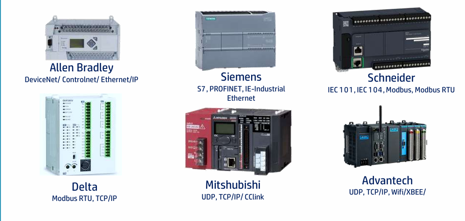
Plc Manufacturers :
